
Premium WordPress theme for construction companies, contractors, builders, and a variety of other construction-related businesses.
-
28238 Kelsie Lane Apt. 451,
Port Annabelport
-
Call Us: (210) 451-123
(Sat - Thursday)
-
Monday - Friday
(10am - 05 pm)
Half-Wet Material Crusher
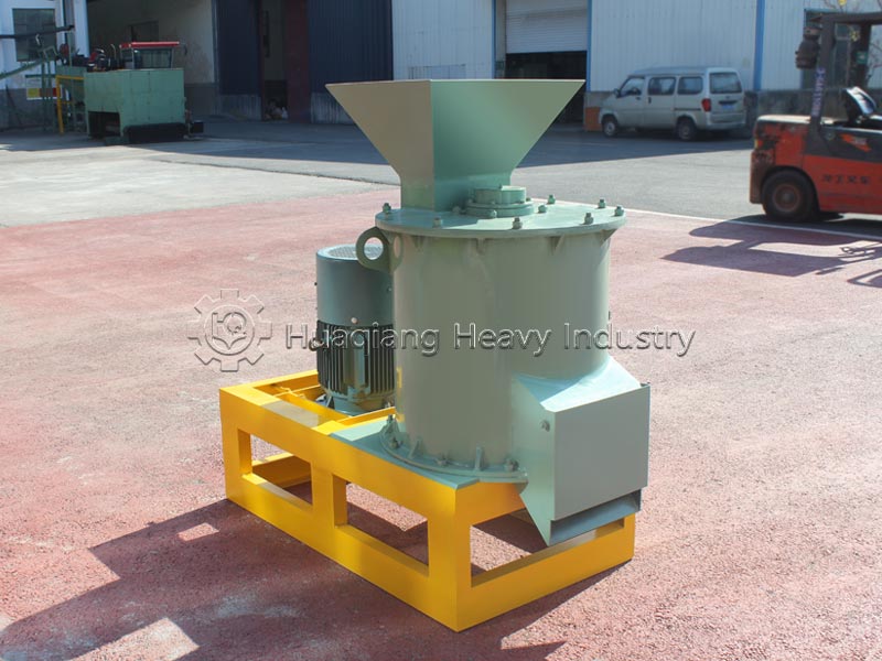
Equipment Introduction
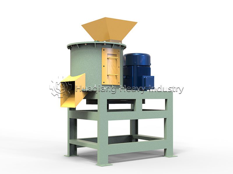
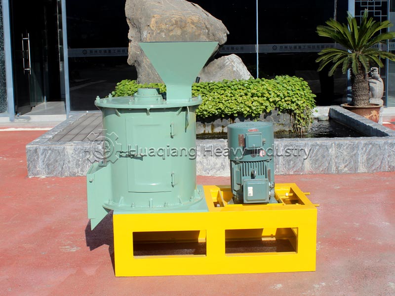
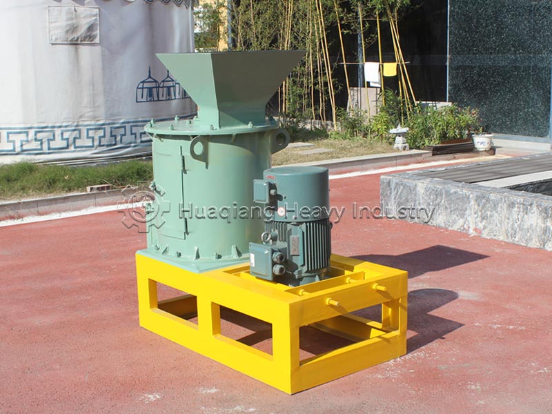
The half-wet material crusher is a specialized crushing equipment designed for processing materials with high moisture content, high fiber content, and high viscosity. Its core design goal is to overcome the technical bottlenecks commonly encountered in traditional crushers when handling materials with high moisture content, such as wall adhesion, clogging, and motor burnout. This equipment is widely used in bio-organic fertilizer production, municipal solid waste composting, livestock manure treatment, and agricultural waste resource utilization.
Compared to traditional hammer crushers or double-roll crushers, the biggest difference of the half-wet material crusher lies in its screenless design and dual-stage rotor structure. It can achieve continuous and stable operation even with material moisture content as high as 25%–55%, completely avoiding problems such as wet material clogging and blockage, significantly reducing equipment failure rate and maintenance costs. The successful development of this equipment plays a crucial role in shortening the process flow, reducing equipment investment, and saving operating costs in bio-organic fertilizer and compost production.
Equipment Structure
The half-wet material crusher can be generally divided into three main parts: the frame, the rotor crushing section, and the transmission connection section.
- Frame Section
The frame provides a stable support foundation for the normal operation of the equipment. It is entirely welded from high-quality carbon steel plates and channel steel, and has passed strict product process requirements.
- Rotor Crushing Section
The rotor crushing section is the core crushing component of the entire equipment. Its structure is novel and rationally designed:
Double-layer blade (hammer) design: Utilizing a double-layer blade crushing system, the crushing effect is twice that of ordinary products. After the material enters the crushing chamber through the feed inlet, it is continuously ground by the double-layer blades until it meets the granulation requirements.
Dual-stage rotor series structure: Some models adopt a dual-stage rotor or upper and lower rotor series crushing structure. The material first enters the upper rotor crushing zone, where it is initially crushed into fine particles by the impact of the high-speed rotating hammers, and then thrown into the lower rotor crushing zone for further fine crushing.
Wear-resistant materials: Hammers and blades are made of high-alloy wear-resistant materials (such as forged high-alloy hammers, 65Mn spring steel, etc.) to enhance durability.
Screen-free design: The equipment is designed without a screen, eliminating clogging problems at the source.
High-strength lining: The internal lining is made of high-strength material to protect the machine casing from wear.
Pusher device: An internal pusher prevents material from sticking to the inner wall.
- Transmission connection: The transmission connection uses a flexible belt drive. The motor drives the pulley and belt, directly transmitting power to the main shaft, causing it to rotate at high speed to achieve the crushing effect. Some units are equipped with a centralized lubrication system, allowing for lubrication without stopping the machine during normal operation.
Working Principle of the Equipment
The half-wet material crusher is primarily designed based on the principle of high-speed impact and grinding. Its core working method is as follows:
- Two-stage rotor series crushing (mainstream model)
The equipment mainly adopts a two-stage rotor series operation design:
First-stage crushing: After entering through the feed inlet, the material first enters the upper rotor crushing zone. Under the violent impact of the high-speed rotating hammers (blades), the material is initially crushed into fine particles.
Second-stage fine crushing: The initially crushed material is then thrown into the lower rotor crushing zone, where it is further finely crushed by the high-speed hammers. During this process, the material particles collide and grind against each other at high speed within the inner cavity.
“Hammer-to-material, material-to-material” effect: Through two-stage crushing, the material is simultaneously subjected to the impact of the hammers and the mutual collision and grinding between particles, achieving a dual crushing effect of “hammer-to-material, material-to-material”.
Finished product discharge: The final product is a fine powder that meets the requirements, which is discharged directly from the outlet.
- Single-Rotor Reversible Type
In addition to the two-stage rotor type, this equipment also exists as a “single-rotor reversible” type, used for grinding materials with specific moisture contents.
- Core Operating Features
Screenless Particle Size Control: The equipment has no screen or sieve bottom; the output particle size is controlled by adjusting the gap between the hammers and the liner.
High-Speed Rotation: The main shaft rotates at high speed driven by an electric motor, generating a powerful impact force.
Continuous Operation: Supports continuous feeding and uninterrupted operation.
Equipment Parameters
The table below shows the rated capacity for processing well-rotted chicken manure with a moisture content of 30%~35% and an output particle size of 0.5~5mm. Capacity decreases by 20%~40% when the material moisture content increases or the particle size is adjusted:
| Model | Matching Motor Power | Standard Capacity (t/h) | Discharge Particle Size Range (mm) | Overall Dimension (L × W × H, mm) |
|---|---|---|---|---|
| BSFS-40 | 15kW | 1~2 | 0.5~5 | 1250×550×1150 |
| BSFS-60 | 22kW | 2~4 | 0.5~5 | 1550×750×1500 |
| BSFS-80 | 37kW | 3~6 | 0.5~5 | 1720×920×1500 |
| BSFS-110 | 55kW | 4~10 | 0.5~5 | 2270×1250×1700 |
Complete Operation and Maintenance Process of Half-Wet Material Crusher
| Module Classification | Item Name | Detailed Content / Operation Standard |
|---|---|---|
| Pre-start Inspection (Daily) | Hardware Safety Check (Power-off Status) | Check all bolts without looseness or falling off; check crushing blades free of bending, fracture and looseness; check fixing pins intact; V-belt tension suitable with sag 10~15mm as standard. Clean feeding, crushing and discharging cavities, remove bulk materials and impurities; confirm access door and safety guard installed properly. |
| Pre-start Inspection (Daily) | Lubrication System Check | Main shaft oil level within standard range; replace deteriorated lubricant if oil turns black, sticky or contains impurities; all grease nipples unobstructed to ensure normal oil supply. |
| Pre-start Inspection (Daily) | Material Pre-treatment Check | Material moisture controlled at 25%~50% to avoid sticking; pre-screening device works normally to prevent foreign hard objects; large materials pre-screened, feeding particle size not exceeding maximum allowable value of equipment. |
| Standard Startup Procedure | Pre-start Confirmation | Confirm all pre-checks completed and safety control circuit closed. |
| Standard Startup Procedure | No-load Startup | Start equipment under no-load condition and run for 3~5 minutes. |
| Standard Startup Procedure | No-load Inspection | Listen for abnormal noise and violent vibration; check normal bearing temperature and correct rotor rotation; stop machine immediately if rotating reversely. |
| Standard Startup Procedure | Feeding Operation | Feed materials slowly and uniformly after stable no-load operation; prohibit one-time bulk feeding; maintain stable feeding during production; avoid long-term overload operation. |
| Operation Monitoring & Abnormality Handling | Motor Current Monitoring | Normal range: 70%~90% of rated current; abnormal standard: continuous over-limit or sudden fluctuation; emergency treatment: reduce feeding volume, stop machine immediately if no improvement. |
| Operation Monitoring & Abnormality Handling | Bearing Temperature Monitoring | Normal range: ≤70℃; abnormal standard: >70℃, rapid temperature rise and hot surface; emergency treatment: stop machine for lubrication inspection, check bearing wear and rotor misalignment. |
| Operation Monitoring & Abnormality Handling | Motor Temperature Monitoring | Normal range: ≤80℃; abnormal standard: hot housing with burnt smell; emergency treatment: stop machine for cooling, check phase loss, overload and blockage of heat dissipation. |
| Operation Monitoring & Abnormality Handling | Discharge Particle Size Monitoring | Normal range: 0.5~5mm, uniform without large lumps; abnormal standard: increased proportion of coarse particles; emergency treatment: stop machine to adjust liner clearance and check blade wear. |
| Operation Monitoring & Abnormality Handling | Whole Machine Vibration Monitoring | Normal: slight vibration, stable anchor bolts; abnormal standard: violent shaking and loose foundation bolts; emergency treatment: stop machine to inspect rotor balance, blades and foundation fixation. |
| Standard Shutdown Procedure | Stop Feeding | Stop feeding equipment first; run main machine under no-load for 3~5 minutes to empty materials inside cavity. |
| Standard Shutdown Procedure | Machine Power-off | After material discharging, cut off main power and hang maintenance warning sign. |
| Standard Shutdown Procedure | Post-shutdown Cleaning | Open access door, clean sticky materials inside cavity to prevent material caking. |
| Periodic Maintenance | Daily Maintenance | Clean residual powder; inspect blades, belts and bolt appearance; standard: no material residue, intact blades and undamaged belts. |
| Periodic Maintenance | Maintenance every 100~200 working hours | Fully inspect blade wear condition, clean feeding device, calibrate rotor balance; standard: blade wear within allowable range, rotor free of shaking. |
| Periodic Maintenance | Weekly Maintenance | Clean liner, add grease to lubrication points, calibrate blade clearance, fasten bolts; standard: bearing grease filled to 2/3, clearance meets discharging requirements. |
| Periodic Maintenance | Quarterly Maintenance | Thoroughly clean bearing housing and replace all lubricant; standard: discharge old grease completely and fill new high-temperature lubricant. |
| Periodic Maintenance | Maintenance after 2000 operation hours | In-depth overhaul of rotor balance, main shaft clearance, circuit and dust removal pipeline; standard: stable rotor, no circuit aging and unobstructed pipeline. |
| Periodic Maintenance | On-demand Maintenance | Replace blades when wear reaches 1/3 or replace in whole set; standard: mixing old and new blades forbidden; recheck rotor balance after replacement. |
| Special Lubrication Regulation | Lubrication for New Machine | Fill lubricant completely before the first startup of new machine. |
| Special Lubrication Regulation | Regular Oil Replacement | Main bearing grease replaced every 3 months; replenish grease every 7 days under 24-hour continuous production. |
| Special Lubrication Regulation | Oil Application Specification | Mixing different types of lubricating grease is prohibited, avoiding bearing dry wear caused by grease deterioration. |
Applicable Raw Materials for the Equipment
Preferred Materials
- Organic Fertilizer Fermentation Raw Materials (Mainstream Scenarios): Well-rotted chicken manure, cow manure, pig manure, sheep manure, and other livestock and poultry manure; mushroom residue, traditional Chinese medicine residue, sugarcane filter mud, distiller’s grains, humic acid; straw + manure mixed fermentation material; urban sludge, kitchen waste fermentation residue.
- Solid Waste Resource Utilization Materials: Garden debris, straw compost, livestock bedding, organic waste fermentation material.
- Other Organic Raw Materials: High-moisture fermented cake, water-containing leaf mold, biogas residue and biogas slurry sediment solids.
Material Moisture Content Suitable Range: Standard operating conditions allow for stable processing of materials with a moisture content of 25%~55%; the optimal operating range is 30%~40%, with the highest crushing efficiency and minimal blade wear; for moisture content >55%, moderate drying is recommended to reduce blade adhesion and wear.
Materials Prohibited from Input: Hard foreign objects such as metal blocks, stones, and pebbles; dry and hard ores with a compressive strength > 80MPa; brittle dry fertilizer clumps (suitable for cage crushers); extra-long whole logs and thick plastic film (easily entangle the rotor blades).
Applications of the Equipment
The half-wet material crusher has a wide range of applications, mainly focusing on the following aspects:
- Organic Fertilizer and Bio-organic Fertilizer Production
The half-wet material crusher is a core crushing equipment in the organic fertilizer production industry, and is the core equipment in the post-fermentation clinker crushing and homogenization chemical section of the organic fertilizer production line. It is widely used in:
Livestock and poultry manure treatment (chicken manure, pig manure, cow manure, sheep manure, etc.); rural straw and garbage crushing; peat moss crushing; mushroom residue crushing; traditional Chinese medicine residue crushing; biogas residue treatment
- Urban Solid Waste and Sludge Treatment
Urban solid waste composting treatment; urban sludge treatment; resource utilization treatment of kitchen waste
- Industrial Organic Waste Treatment
Wine and sugar factory waste treatment; industrial organic waste treatment; chemical raw material crushing
- Grinding of Hard Impurities
The half-wet material crusher grinds hard materials such as glass, ceramics, bricks, and gravel in urban solid waste and organic fertilizer raw materials, making them safe for application.
Application of the Equipment in the Production Line
In organic fertilizer and bio-fertilizer production lines, the half-wet material crusher is typically located after the fermentation process and before the granulation process, serving as a key connecting link between the preceding and following processes:
- Process Location
Raw material pretreatment → Fermentation turning → [half-wet material crusher] → Batching and mixing → Granulation → Drying → Cooling → Screening → Packaging
- Process Benefits:
1) Shortened Process Flow: Traditional processes require drying and then pulverizing high-moisture fermented materials. half-wet material pulverizers can directly process fermented materials with a moisture content of 25%–50%, eliminating the pre-drying step and significantly reducing energy consumption and equipment investment.
2) Improved Granulation Quality: Pulverizing fermented materials to a uniform fine powder of 0.5–5mm results in higher pelleting rates and more uniform particles in subsequent granulators (such as rotary drum granulators and disc granulators).
3) Grinding Hard Objects: Grinding hard impurities such as glass, ceramics, bricks, and gravel mixed in the material prevents damage to subsequent granulation equipment.
4) Adaptable to Multiple Formulas: Whether it’s pure livestock and poultry manure, straw-manure mixtures, or bio-organic fertilizers with added microbial agents, the pulverization fineness can be adjusted to meet different formula requirements.
- Integration with Supporting Equipment
1) Front End: Connects to fermentation equipment (trough-type compost turner, tracked compost turner) to receive the half-wet material after fermentation;
2) Back End: Connects to automatic batching system, mixer, and granulator to provide raw materials with qualified particle size for granulation;
3) Dust Removal Support: It is recommended to install a dust removal system at the inlet and outlet to reduce dust concentration in the workshop and improve the working environment.
Common Equipment Faults and Solutions
| Fault Category | Cause Analysis | Solution | Preventive Measures |
|---|---|---|---|
| Bearing Temperature Abnormal (≥70℃) | 1. Insufficient or deteriorated lubricant 2. Bearing damage or excessive clearance 3. Rotor misalignment or unbalance 4. Long-term overload operation | 1. Stop machine and replenish or replace grease 2. Check bearing wear and replace damaged bearing 3. Calibrate rotor alignment and dynamic balance 4. Reduce feeding volume and stabilize load | 1. Inspect lubrication status before each shift 2. Replace grease every 3 months 3. Monitor bearing temperature during operation 4. Avoid continuous overload production |
| Motor Overheating / Overload Tripping | 1. Overfeeding or material blockage 2. Voltage instability or phase loss 3. Motor fan damaged or air duct blocked 4. Insufficient power matching | 1. Stop feeding immediately, clear blockage and restart 2. Check power supply, cable and contactor 3. Clean motor fan and cooling air duct 4. Replace with reasonably matched motor if necessary | 1. Keep feeding uniform and stable 2. Monitor current and voltage fluctuations 3. Clean motor ventilation system monthly 4. Prevent startup with materials |
| Vibration Abnormality / Metal Collision Noise | 1. Rotor unbalance after blade replacement 2. Loose or broken blade/hammmer 3. Hard foreign objects entering crushing chamber 4. Loose anchor bolts or foundation instability | 1. Stop machine to check blade fastening and wear 2. Clear metal and hard impurities inside cavity 3. Perform rotor dynamic balance calibration 4. Tighten anchor bolts and reinforce foundation | 1. Check blade status before each startup 2. Install magnetic separator and grid at feed inlet 3. Avoid mixed use of new and old blades 4. Check foundation fastening daily |
| Discharge Particle Size Too Coarse or Too Fine | 1. Blade wear beyond limit 2. Improper gap between blade and liner 3. Screen mesh damaged or blocked 4. Rotating speed mismatch | 1. Replace severely worn blades 2. Adjust clearance between blade and liner 3. Clean or replace screen mesh 4. Adjust rotor speed according to material requirements | 1. Check blade wear weekly 2. Keep crushing clearance consistent 3. Inspect screen condition after shutdown 4. Forbid random parameter adjustment |
| Feeding Inlet Blockage / Material Bridging | 1. Material moisture too high or viscosity strong 2. Feeding speed too fast 3. Foreign objects blocking feed inlet 4. Unsmooth material discharging | 1. Stop machine to clear blocked materials 2. Reduce feeding speed and stabilize feeding volume 3. Remove foreign hard impurities 4. Check and clean discharge pipeline | 1. Control material moisture within allowable range 2. Install pre-screening device at feed inlet 3. Prohibit clearing blockage during operation 4. Keep feeding continuous and uniform |
| Belt Slipping / Abnormal Wear | 1. Belt tension too loose 2. Pulley misalignment or wear 3. Overload startup or frequent startup 4. Belt aging or oil contamination | 1. Adjust belt tension to standard sag 10~15mm 2. Check pulley alignment and replace worn pulley 3. Clean oil contamination on belt surface 4. Replace cracked or aged belt | 1. Check belt tension daily 2. Avoid startup with heavy load 3. Keep belt and pulley clean 4. Replace belts regularly according to wear status |
Target Customers for Equipment:
- Large-scale organic fertilizer production enterprises: Plants producing organic fertilizer from livestock and poultry manure, bio-fertilizers, and humic acid fertilizers; core purchasing group.
- Small and medium-sized livestock and poultry farms supporting fertilizer processing plants: Chicken farms and pig farms with self-built manure resource utilization processing workshops.
- Urban solid waste treatment enterprises: Kitchen waste treatment stations, municipal sludge treatment centers, and garden waste resource utilization bases.
- Manufacturers of microbial inoculants and substrate nutrient soil: Enterprises processing seedling substrates, flower nutrient soil, and microbial residue.
- Organic fertilizer complete equipment engineering companies: General contractors for fertilizer production lines and equipment export manufacturers.
- Small-scale composting stations in villages and towns, and agricultural cooperatives: Small-scale production lines for centralized fermentation and fertilizer production by individual households.
- Enterprises utilizing agricultural and sideline waste such as medicinal herb residue, distiller’s grains, and sugarcane filter mud.
Performance Characteristics and Core Advantages of the Equipment
The core advantages of the half-wet material crusher include:
- Screen-free and anti-clogging: No screen or sieve bottom is designed, allowing for the crushing of over a hundred types of materials. High-moisture materials will not clog, and even materials just retrieved from water can be processed normally.
- Dual-stage high-efficiency crushing: The upper and lower rotors work in series, achieving twice the crushing efficiency of single-stage equipment, with uniform output particle size.
- High-alloy wear-resistant parts: The hammers are made of forged high-alloy wear-resistant material, making them strong, wear-resistant, and with a service life far exceeding that of ordinary hammers.
- Two-way gap adjustment technology: Wearing hammers requires no repair; they can be moved for continued use. The output particle size can be controlled by adjusting the gap.
- Simple operation and maintenance: Single-person operation of multiple machines; centralized lubrication system supports non-stop oiling, resulting in low maintenance costs.
- Energy consumption advantage: The overall power consumption is reduced by more than 25% compared to traditional crushers, meeting the industry standard of “Organic Fertilizer Processing Equipment” (JB/T 1093-2018).
- Fully enclosed and environmentally friendly: The equipment operates in a closed system, and with the dust removal system, the dust leakage rate is extremely low, meeting environmental protection requirements.