
Premium WordPress theme for construction companies, contractors, builders, and a variety of other construction-related businesses.
-
28238 Kelsie Lane Apt. 451,
Port Annabelport
-
Call Us: (210) 451-123
(Sat - Thursday)
-
Monday - Friday
(10am - 05 pm)
Drum Fertilizer Dryer

Equipment Introduction
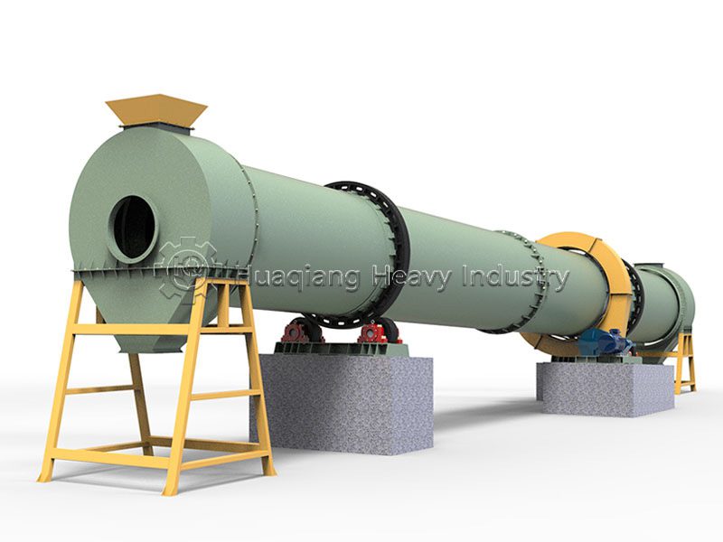
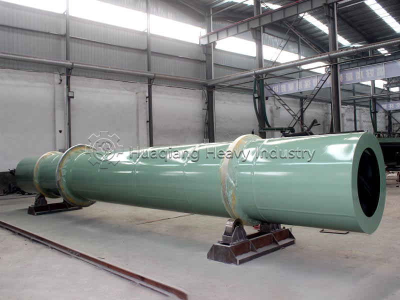
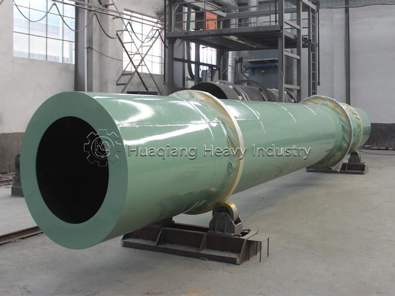
The fertilizer rotary dryer machine, also known as a rotary fertilizer dryer, is a core dehydration equipment in organic fertilizer and compound fertilizer production lines. It is a nationally promoted environmentally friendly technology model, specifically developed for dehydrating fertilizer granules and high-moisture organic waste.
Core Advantages
Wide Capacity Adaptability: Hourly capacity 1~16t, customizable, suitable for fertilizer plants with an annual capacity of 10,000~500,000 tons;
Uniform Drying and Energy Saving: Built-in optimized lifting plates ensure thorough heat exchange between hot air and material, achieving a thermal efficiency ≥70% and zero emissions;
Stable and Durable Operation: Wear-resistant and corrosion-resistant materials, 24-hour continuous production, low maintenance frequency, and low operating costs;
Strong Material Compatibility: Choose between co-current and counter-current airflow paths, accommodating both high-moisture manure and heat-sensitive fertilizer granules;
Complete Support: Can be integrated with hot air furnaces, coolers, dust collectors, screening, and packaging to form a complete automated production line.
Equipment Function: After granulation, fertilizer has a high moisture content of 25% to 45%, making it extremely prone to clumping, mold growth, and nutrient loss. The dryer reduces the moisture content of the material to 2% to 10%, reducing the risk of clumping during storage, locking in nutrients, and reducing transportation weight. It is an essential process for the commercialization of fertilizer.
Structural Components of the Equipment
The fertilizer rotary drum dryer can be divided into five main components:
- Drum Body (Machine Body)
The drum body is the most important part of the entire dryer, welded from high-quality medium carbon steel plates. The dryer is a cylinder slightly inclined (usually 2-5 degrees) to the horizontal. Lifting plates (lifting plates) are installed on the inner wall of the drum, made of high-quality wear-resistant materials, with a reasonable distribution angle design. Their function is to continuously lift and scatter the material, ensuring full contact between the material and the hot airflow.
- Support Frame and Support Section
The rotating parts of the entire machine body are supported by the support frame, which bears a significant load. The roller support frame is welded from medium carbon steel plates and channel steel. The rollers fixed to the frame are made of high-quality anti-corrosion and wear-resistant materials, greatly improving service life. The roller support frame adopts integrated casting technology, with lifting holes at the four corners for easy loading, unloading, and transportation. Key components include the front roller ring, rear roller ring, guide roller, and drag roller.
- Transmission Section
The transmission section is the core that drives the entire machine. The transmission frame is welded from high-quality channel steel, and the main motor and reducer mounted on the transmission frame are both reliable products. The motor drives the pulley, V-belt, and reducer to transmit power to the transmission shaft. A small gear mounted on the transmission shaft meshes with a large gear ring fixed to the machine body, driving the machine to rotate.
- Feeding, Discharging, and Sealing Devices
Feeding End: Equipped with a feeding hopper and feeding pipe; material is added from the higher end.
Discharging End: Equipped with a discharge port and a star-shaped discharge valve.
Sealing Ring: Ensures a tight system seal, preventing leakage of hot air and dust.
- Auxiliary Equipment
A complete drying system also includes: a heat source device (coal, natural gas, steam, biomass pellets, etc.), a feeder, an induced draft fan, dust collection equipment (bag filter, cyclone dust collector, desulfurization scrubbing tower, etc.), and a power distribution cabinet.
Applications of the equipment
Fertilizer dryers have a very wide range of applications:
| Application Field | Typical Materials |
|---|---|
| Organic Fertilizer | Livestock manure (chicken manure, cow manure, pig manure), sludge, biogas residue, straw powder, kitchen waste |
| Compound Fertilizer | NPK compound fertilizer, Mono‑Ammonium Phosphate (MAP), Di‑Ammonium Phosphate (DAP), Triple Superphosphate (TSP) |
| Inorganic Fertilizer | Ammonium sulfate, ammonium nitrate, potassium chloride, potassium sulfate, urea granules |
| Soil Conditioner | Gypsum, limestone powder, humic acid, biochar |
| Others | Feed raw materials, bagasse, distiller’s grains, medicinal residues, mineral slag |
Applicable Raw Materials (Scope of Materials to be Processed)
- Organic Raw Materials (High Moisture and Binding Materials)
Livestock and poultry manure such as chicken manure, cow manure, pig manure, and sheep manure; organic waste such as straw, mushroom residue, distiller’s grains, medicinal residue, sugarcane filter mud, kitchen sludge, peat, and slaughterhouse by-products; fermented and decomposed organic fertilizer and semi-finished bio-organic fertilizer.
- Inorganic/Compound Fertilizer Granules
Drum granulation, disc granulation, extrusion granulation compound fertilizer, organic-inorganic compound fertilizer, BB fertilizer, urea-based/sulfur-based/chlorine-based compound fertilizer, amino acid compound fertilizer, spray granulation granular fertilizer.
- General Extended Materials
Various granular and powdery biomass raw materials, slightly sticky chemical granules, sludge, etc.
Working Principle
The entire machine is installed at a slight 2.5° tilt. The motor drives the cylinder to rotate continuously at low speed via a reducer and gear pair:
Feeding and Conveying: High-moisture fertilizer granules are fed into the cylinder from the high-end feed inlet;
Hot Air Heat Exchange: High-temperature hot air is generated by a hot air furnace and drawn into the cylinder under negative pressure by an induced draft fan, with two heat exchange modes: co-current (hot air and material flow in the same direction) and counter-current (hot air flow in opposite directions);
Lifting and Drying: Lifting plates inside the cylinder rotate with the cylinder, continuously lifting and dropping the material at the bottom to form a uniform material curtain. Hot air penetrates the material curtain and removes the internal moisture of the material;
Discharge and Transfer: With the cylinder tilted and the rotational thrust, the material slowly moves to the lower end and is discharged from the outlet after reaching the required drying standard;
Exhaust Gas Treatment: Dust-laden, humid exhaust gas enters a dust collector at the tail end of the cylinder for purification before being released into the atmosphere. The entire process of feeding, drying, and discharging is continuous and automated, enabling large-scale uninterrupted production.
Common Faults, Causes, and Standardized Solutions
| Fault Phenomenon | Root Cause | Professional Solutions |
|---|---|---|
| Undried material, high moisture of discharged material | Insufficient hot air supply; excessive feeding volume; too high cylinder rotating speed; lifting plate falling‑off | 1. Raise hot‑blast stove temperature; 2. Reduce feeding speed; 3. Lower cylinder speed; 4. Stop machine for maintenance and repair lifting plates |
| Riding‑ring offset & partial slipping | Loose riding‑ring joint; unbalanced force on both sides of supporting roller | 1. Fasten riding‑ring arc joint; 2. Adjust supporting roller height evenly with shims to avoid cylinder vibration caused by over‑tightness |
| Cylinder axial displacement & axial shaking | Severe wear of supporting roller & stop roller; loose anchor bolts of supporting roller base | 1. Polish, repair or replace worn supporting / stop rollers; 2. Re‑calibrate supporting roller level and fasten lock nuts |
| Gear meshing abnormal noise & dislocation | Unilateral wear of pinion; loose connection between big gear ring and cylinder | 1. Re‑install pinion; replace directly if double‑sided wear occurs; 2. Calibrate flange between gear ring and cylinder, tighten bolts |
| Violent cylinder vibration during operation | Cracked supporting‑roller base connection, loose bolts; uneven unilateral wear of riding‑ring | 1. Re‑calibrate supporting‑roller position, fasten all anchor bolts; 2. Repair riding‑ring surface or replace riding‑ring |
| Material back‑flow at feeding port & dust overflow | Insufficient induced‑draft fan air volume; aging air leakage of end seals | 1. Inspect fan impeller, adjust air damper to improve negative pressure; 2. Replace flexible sealing parts at feeding & discharging ends |
| Bearing temperature >50℃ (8h no‑load test standard) | Lack of lubricating grease; internal bearing wear | Stop machine and add lubricating grease; replace bearing directly if heavily worn |
Equipment Operation and Maintenance Methods
(I) Start-up Operation
Pre-start Preparation:
Ignite the hot air furnace about half an hour before starting the dryer.
Check the heat source, combustion chamber, feeding device, and auxiliary device transmission.
Remove any stuck material from the charging hopper and chute; clean the combustion chamber.
Check the rotation of the furnace door, air ducts, regulating valves, and blower.
All bearings and all friction surfaces should have an appropriate amount of lubricating material.
Apply grease to gears; apply grease to the roller surface every 7 days.
Start-up Sequence:
Start the dryer motor and induced draft fan motor.
Start the equipment for transporting wet and dry materials.
Ignite the hot air furnace for preheating; feed material only after the cylinder temperature reaches the set value.
(II) Operation During Operation
Uniform Feeding: Configure a quantitative feeding device, linked with the hot air temperature and cylinder rotation speed for control.
Temperature Monitoring: Monitor the inlet flue gas temperature and outlet exhaust gas temperature in real time.
Safety Precautions:
Do not add fuel to the hot air furnace while the air supply is running to avoid scratches.
Do not start the furnace while the air supply is running. Door
When the dryer is running, it is forbidden to pass under the machine body.
During the operation of the dryer, it is forbidden to perform internal inspections and repairs.
The dryer must not be started without a proper grounding wire.
(III) Shutdown Operation
Shutdown Procedure:
Fueling should be stopped 30 minutes before the dryer is shut down.
Adding materials to the dryer should be stopped.
The dryer drive motor should be turned off.
The equipment transporting dry materials should be stopped.
(IV) Maintenance
Lubrication Maintenance: Replace the grease in the bearing chamber every 3 months; the reducer must be filled with gear oil before use and then replaced every 4 months thereafter; regularly lubricate the support rollers, thrust rollers, and drive gears.
Regular Cleaning: After each shift, remove residual materials and check the wear of the lifting plates.
Regular Inspection: Regularly check the rotation flexibility of rotating parts and whether there is any jamming; regularly open the cleaning door to clean the materials adhering to the inside of the cylinder and the inlet and outlet chambers.
Support Roller Maintenance: Perform maintenance work on the support rollers to prevent wear on the surface of the support rollers; the solid adhering material inside the drying cylinder should not be uneven, otherwise it will easily lead to uneven wear of the tires.
Equipment capacity range:
General inlet air temperature <700℃, uniform cylinder inclination angle 2.5°, final material moisture content controllable from 2% to 10%.
| Model No. | Diameter × Length of Cylinder (mm) | Cylinder Speed (r/min) | Hourly Capacity (t/h) | Matching Motor Power (kW) |
|---|---|---|---|---|
| ZG08800 | Φ800×8000 | 8 | 1~1.5 | 4 |
| ZG10100 | Φ1000×10000 | 7 | 1.5~2 | 5.5 |
| ZG12120 | Φ1200×12000 | 7 | 2~2.5 | 7.5 |
| ZG15120 | Φ1500×12000 | 6 | 3~6 | 11 |
| ZG15150 | Φ1500×15000 | 6 | 3~7 | 15 |
| ZG18180 | Φ1800×18000 | 5 | 7~10 | 22 |
| ZG20200 | Φ2000×20000 | 3.9 | 8~14 | 22 |
| ZG22220 | Φ2200×22000 | 3.2 | 12~16 | 30 |
Customized services: We can customize larger diameter/longer cylinder models according to the initial moisture content of raw materials and annual production requirements, suitable for large-scale fertilizer bases with an annual output of more than 500,000 tons.
Target Customers for Fertilizer Dryers:
- Organic Fertilizer Manufacturers: Manufacturers using livestock manure and agricultural waste as raw materials to produce commercial organic fertilizers.
- Compound (Mixed) Fertilizer Plants: Enterprises producing inorganic or organic-inorganic compound fertilizers such as NPK, ammonium phosphate, and ammonium sulfate.
- Large-Scale Livestock Farms: Enterprises with their own manure treatment centers that need to convert manure into organic fertilizer or fuel pellets.
- Sludge Treatment and Environmental Protection Companies: Projects involving the drying and resource utilization of municipal sludge and industrial organic sludge.
- Biomass Energy Enterprises: Enterprises that dry distiller’s grains, medicinal residues, and straw to produce biomass fuel or feed.
- Soil Remediation and Conditioner Manufacturers: Manufacturers of soil conditioners such as gypsum, limestone, and humic acid.
Equipment Application in Production Lines
In modern fertilizer production lines, the dryer is typically located after the granulator and before the cooler, forming a standard process chain of “granulation → drying → cooling → screening → packaging”:
Fermentation/Ingredient Mixing → Crushing → Mixing → Granulation → Dryer → Cooler → Screening Machine → Coating Machine → Packaging Machine
Process Functions:
- Secondary Dehydration: Reduces the moisture content of granulated particles from approximately 15%–25% to ≤10%, meeting storage and transportation standards.
- High-Temperature Sterilization: Temperatures above 80°C during drying kill residual pathogens, insect eggs, and weed seeds in the material.
- Granule Polishing: The rotating drum polishes the granules, improving their appearance and marketability.
- Connection and Buffer: As a key node in a continuous production line, it balances the capacity fluctuations between upstream and downstream stages. For organic fertilizer production lines, a dryer can also be set up after fermentation and before granulation to reduce the moisture content of fermented materials from 40% to about 20%, which facilitates subsequent crushing and granulation.
Analysis of the advantages and disadvantages of the equipment
| Category | Description |
|---|---|
| Advantages | 1. Large processing capacity: hourly output of single unit reaches 1‑16 tons, suitable for large‑scale continuous production. 2. High drying efficiency: materials with moisture content of 70%‑80% can be dried to below 13% in one pass. 3. High thermal efficiency: thermal efficiency can reach more than 70%. 4. Strong adaptability: capable of handling materials with various characteristics. 5. Flexible operation: adapt to different working conditions by adjusting rotating speed, temperature, feeding rate and other parameters. 6. Stable and reliable operation: strong overload resistance, smooth cylinder running. 7. Sealed operation: the whole process runs in closed system to reduce environmental pollution. 8. Bactericidal function: pathogenic bacteria and insect eggs can be killed during drying. 9. Good expandability: production margin is reserved in design; slight output increase does not require equipment replacement. |
| Disadvantages | 1. High investment: large‑size dryer together with matched heat source and dust‑removal system requires high capital cost. 2. High energy consumption: continuous heat supply is required, leading to high operating cost. 3. Temperature control for heat‑sensitive materials: organic fertilizer materials are temperature‑sensitive; precise temperature control is needed to avoid nutrient loss. 4. Dust‑removal equipment required: dust collection system must be equipped to meet environmental‑protection requirements. 5. High maintenance requirement: supporting rollers, gears, bearings and other components need regular lubrication and maintenance. 6. Large footprint: large rotary dryer can be over 20 meters long, requiring large installation space. 7. Requirement for material particle size: large lumps and agglomerates in raw materials shall be crushed in advance. |